
ezy2392 is a compact controller that companies use to manage machine I/O and communication. It offers a small footprint, flexible connectivity, and low power draw. This guide explains what it is, how it works, and how to set it up.
Table of Contents
ToggleKey Takeaways
- ezy2392 is a compact DIN-rail controller that consolidates 12 digital inputs, 8 outputs, Ethernet, RS-485, and USB to simplify machine I/O and wiring.
- Follow the step-by-step setup: mount on a DIN rail, connect 24V DC and earth, attach Ethernet/USB, access the web interface, set an admin password, map I/O, and test each channel.
- Use the built-in Modbus RTU/TCP support and web-based configuration for easy network integration and remote monitoring without a PLC.
- Troubleshoot common issues by checking supply voltage and polarity for power faults, verifying Ethernet cables/IP for network problems, and confirming wiring and input configuration for I/O errors.
- Maintain reliability with biannual inspections, firmware checks, event log reviews, torque terminal screws, and keeping spare units on site.
What EZY2392 Is And Why It Matters
ezy2392 is a hardware controller that integrates input, output, and network interfaces. It connects sensors, actuators, and supervisory systems. Engineers choose it for its simple design and predictable behavior.
It matters because it reduces component count and simplifies wiring. It lowers installation time and lowers operational error rates. It also supports common industrial protocols, so it fits into existing systems.
The device ships with firmware that handles I/O mapping, event triggers, and basic logic. Users can update the firmware to add features. Manufacturers publish a datasheet that lists electrical and mechanical limits. Technicians read this datasheet before they install the unit.
Key Specifications And Features
EZY2392 offers a set of clear specifications. It supports 12 digital inputs and 8 digital outputs. It accepts 24V DC power and draws under 3W in typical use. The unit operates from -20°C to 60°C.
It includes an Ethernet port and an RS-485 port. It supports Modbus RTU and Modbus TCP. It also offers a USB port for local configuration. The enclosure uses an IP20 rating for indoor installation.
The firmware supports configurable input filtering and output timing. It logs up to 10,000 events in local memory. It supports password-protected access for setup. The hardware includes LED indicators for power, link, and error states.
The feature set favors reliability and predictable operation. It does not include a touchscreen. It does include a web-based configuration interface that works on standard browsers. The interface shows I/O status, logs, and basic diagnostics.
Typical Use Cases And Target Users
Companies use ezy2392 in factory automation for conveyor control and simple machine control. Integrators use it for remote monitoring of pumps and fans. Maintenance teams use it as a low-cost replacement for legacy modules.
System designers use the unit when they need clear I/O mapping and easy network access. Field technicians use it when they need quick diagnostics on site. Small manufacturers use it when they want to add networked control without a PLC.
The product suits environments that need simple logic, event logging, and basic network access. It does not suit high-speed motion control or tasks that need complex sequencing. It fits well in applications that value reliability, clear status feedback, and simple configuration.
Installation And Initial Setup
Installers mount the unit on a DIN rail in a protected panel. They secure wiring to the terminal blocks and verify polarity. They connect earth ground to the chassis when the panel requires grounding.
They apply 24V DC and check the power LED. They attach the network cable and check the link LED. They connect a laptop to the USB port if they need to run local setup.
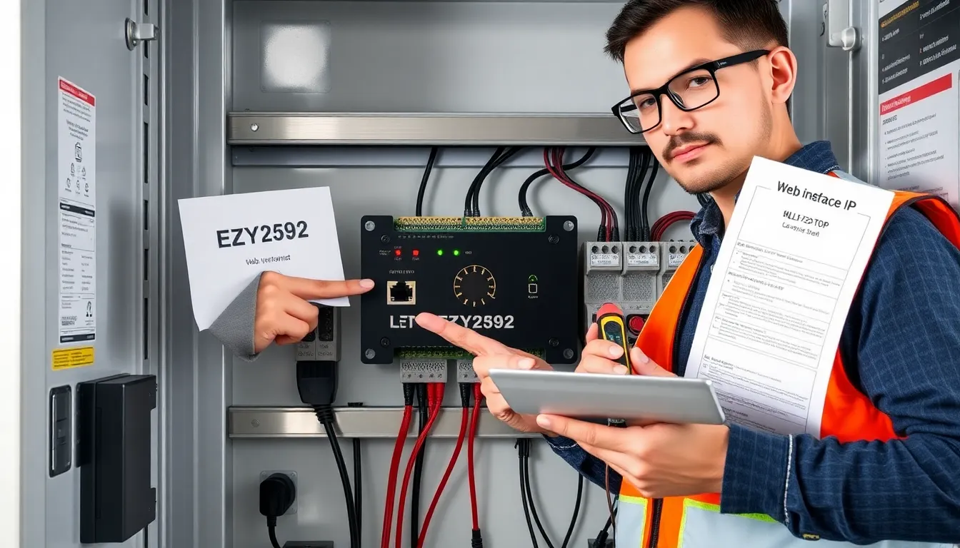
After power-up, the unit boots and shows default configuration. The installer reads the IP address from the display or uses the DHCP server to assign one. The installer then opens the web interface to complete the setup.
Step-By-Step Setup Checklist
- Unpack the unit and inspect it for damage.
- Mount the unit on a DIN rail.
- Connect 24V DC supply to the power terminals.
- Connect earth ground if required.
- Wire inputs and outputs to the correct terminals.
- Attach the Ethernet cable to the network port.
- Power the unit and confirm the power LED.
- Access the web interface using the IP address.
- Set the admin password and save it securely.
- Map inputs and outputs to their functions.
- Test each input and output and record the results.
- Update the firmware if an update is available.
Common Problems And How To Troubleshoot Them
The most common problems include no power, network failure, and incorrect I/O mapping. Each problem has focused checks that reveal the cause.
If the unit does not power, check the supply voltage at the terminals. Check for blown fuses in the panel. Check for reversed polarity if the install uses nonstandard wiring.
If the network link is down, check the Ethernet cable and switch port. Verify that the unit has a valid IP address. Ping the unit from a laptop to confirm network reachability.
If inputs do not change state, verify wiring and sensor power. Use a multimeter to confirm signal presence at the terminal. Check input configuration for correct polarity and pull-up settings.
Best Practices For Maintenance And Longevity
Operators should schedule routine inspections every six months. They should clean the panel to remove dust and debris. They should check terminal screws and re-torque them if they loosen.
They should run a firmware check twice per year. They should record firmware versions and change logs. They should keep spare units on site when downtime has high cost.
They should monitor event logs for recurring errors. They should replace sensors and cables that show intermittent faults. They should keep the environment within the rated temperature range.
Further Resources, Documentation, And Where To Learn More
The manufacturer provides a user manual that lists pinouts, electrical limits, and error codes. The manual also shows the web interface and configuration steps. Technicians download the manual from the vendor support page.
The vendor publishes firmware updates and release notes on the same page. Integrators consult the Modbus specification for protocol details. Field staff use online forums to see common issues and fixes.
They should contact vendor support for warranty and replacement details. They should keep a copy of the latest datasheet with the device for quick reference. They should join technical groups that focus on simple controllers and industrial I/O.